- By Ralph O'Quinn
 There are more and more of you out there fixing up old rods, even fixing up
not so old rods. Your high-end graphite fly rods, spin rods, plug casting
rods, etc., are not noted for their ruggedness or durability. They are noted
for their delightful handling characteristics and their not so delightful
cost. It almost seems as though the higher the cost - the easier they break.
The manufacturers of these rods usually have an unconditional warranty.
Stomp on it, run over it with your pickup - whatever - they will replace it.
But the replacement is not always a painless process. If it gets broken on a
weekend and you want to go fishing the next weekend, you had better have a
substitute rod or two on hand, or else you will find yourself staying home
and thinking about the nice trip you might have had if only . . .
There are more and more of you out there fixing up old rods, even fixing up
not so old rods. Your high-end graphite fly rods, spin rods, plug casting
rods, etc., are not noted for their ruggedness or durability. They are noted
for their delightful handling characteristics and their not so delightful
cost. It almost seems as though the higher the cost - the easier they break.
The manufacturers of these rods usually have an unconditional warranty.
Stomp on it, run over it with your pickup - whatever - they will replace it.
But the replacement is not always a painless process. If it gets broken on a
weekend and you want to go fishing the next weekend, you had better have a
substitute rod or two on hand, or else you will find yourself staying home
and thinking about the nice trip you might have had if only . . .
I'm finding more and more of these high end rods that are repaired - sorta -
then I get them after the repair needs repairing. Ordinarily if a rod is
damaged and the damage is repaired, the manufacturer will not honor the
warranty because it has been altered. So you make your choice - send it back
- or have it repaired. But you don't have it repaired for next week's
long-planned trip, then send it to the manufacturer when you return. It's an
either/or situation, not both.
For some reason more of the older rods are being repaired. I have repaired
lots and lots of rods where the cost of the repair was substantially greater
than what it would have been to replace the rod with a far better one.
Sentimentality is usually involved here and I have no quarrel with that, as
long as all the facts are laid on the table. The repairman must present all
the facts of the poor economics of such, and the repairee must be of legal
age and sound mind.
Quite a few of older rods are also being "re-worked" or "re-furbished", and
the expertise necessary to properly accomplish this job falls within the
repair category. Once a guy has fished with the same rod for 30 years,
caught many a memory and developed a feel for that particular stick - he
doesn't listen to all the hype about the reel seat being rusty and loose,
the handle squishy and half gone, the guides mostly taped on. These things
are irrelevant. He even goes with family and friends to local sports shops
and handles literally dozens of new modern rods of a similar makeup - but
nothing FEELS right. Then he learns about this guy that can make the old rod
new again - at about twice the price of those he looked at in the shop!
Repair Skill
The skills involved in repairing a rod can be more demanding than the skills
involved in building a rod. This statement, of course, will be challenged by
the many fine craftsmen engaged in producing the excellent custom rods so
prevalent in our fishing society, especially by those who have mastered
thread art and specialize in beautiful butt wraps. However, from many of
these fine craftsmen I see a lack of understanding of basic structural
principals as well as a lack of knowledge of rudimentary rod blank
construction. From very competent rod builders I have seen atrocious
attempts at repair of the rod that they so expertly created. I think that a
lot of this has to do with where the heart lies. If your heart isn't in it -
forget it - don't clobber it up just to get it out of your hair. Probably
one of the most common of repair jobs that any of us are asked to perform is
the simple procedure of putting back together two pieces of a rod - usually
tip sections - that were inadvertently separated. I have a few of these jobs
in my shop at the present time, so let's go through the repair of some of
them and analyze the reasoning behind each one. I have selected some that
are very common to all of us, simple tip sections of fly rods and light spin
rods - and progressive in their complexity. All are of graphite
construction.
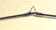
1. A 4-weight fly rod, broken in the center of the guide adjacent to the
tip.
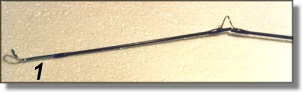
2. A 6-weight fly rod, broken about a foot from the tip, between the second
and third guide.
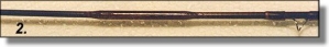
3. Another 4-weight fly rod, broken about 9 inches from the ferrule.
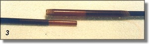
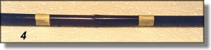
4. A medium-weight spin rod, crushed forward of the gathering guide.
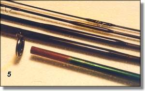
5. A crushed ferrule on a very cheap discount store special fly rod.
OBJECTIVE
When we join two separated sections of a rod, the intent is that the
completed repair be as structurally sound as the original and that it
perform, feel and act as it did before it became disjointed. Therefore it
follows that our repair materiel should represent as closely as possible the
properties that are inherent in the original rod, i.e., have the same
stiffness, flex etc, but it is more important that we maintain the
properties of the ROD itself. It must retain the same balance, the same
flexure, the same power, the same overall properties inherent in the
original design. The only logical manner in which to join these broken rod
tips is to use a tapered tubular section of similar materiel and make a
splice. You wouldn't believe some of the stuff I've removed from repairs
that went sour. Piano wire, small nails, wooden dowels, aluminum tubing,
brass tubing, steel tubing, solid plastic rods like pieces of plastic chop
sticks - you name it. Let's take the repair examples one at a time and
analyze their differences and sameness.
Number 1 - Click For Larger View
Number 1. The fly rod tip broken in the center of the last
guide is a very
common break area. I'm not sure why, maybe the guide was wrapped too tightly
and caused the section to go oval in shape under flex. For whatever the
cause, this is a very common repair area in high modulus fly rods. First we
must remove the guide in such a manner as not to damage or alter the area to
be joined. Not only must the guide be removed, we also must remove all
residual thread finish (epoxy). We must work with a clean section of
graphite in order to obtain a satisfactory splice. This break is quite clean
and all we have to do is a gentle squaring off of the ends. This is done
with a sandpaper block of about 220 grit. The OD of each piece must match as
closely as possible. At this point on the rod, the ID is a nonentity. OK,
now we have two pieces to splice together. What do we splice it with?
Remember that our goal is to maintain the original properties, therefore we
must use the same materiel that is in the rod, right? So we scrounge up a
piece of graphite from an old scrap fly rod and very carefully fashion a
nice fitting sleeve splice, bond it together, and tie the guide in place.
When completed we admire the handiwork and give it a test flex and promptly
break the tip again just forward of the original repair.
What happened?
Our goal is to maintain the 'properties of the rod'; this doesn't mean that
we have to use the same materiel as is in the rod. When we made a graphite
sleeve, we increased the OD of the rod at the repair point. This increased
the "I" moment - stiffness, at that point, and the area on both sides of the
sleeve are subjected to a bending force far beyond their capability. So if a
graphite sleeve won't work on graphite, what do we use? The answer is
simple. Keep in mind that whenever we use a sleeve, we are increasing the OD
of the rod at that point. If we use a materiel of the same modulus, we are
increasing the stiffness to an unacceptable level and inducing a break
adjacent to the sleeve area. The answer is to use a materiel of LOWER
MODULUS so as not to increase stiffness, and that materiel just happens to
be our fiberglass rods. When repairing any graphite section with an external
sleeve, always use a lower modulus materiel. Modulus is defined as STRESS
divided by STRAIN. Think of it as relative stiffness. Now let's do our
splicing correctly.
SPLICING
We have cleaned the repair area of the two pieces to be spliced, a
micrometer shows us that the two pieces are the same diameter, further
miking shows us that there is very little taper at this point on the rod.
Obtain a piece of fiberglass fly rod tip section, cut it to fit snugly over
the end of the main rod section. You will start the joining with a section
about 1&1/2 inch long. Once you are sure that both pieces fit snugly, reduce
the section by tapering the ends to about a 15 degree angle. You will want
to wind up with an overlap of both pieces of about 1/2 inch, the taper will
consume about 1/8 inch, so your structure is about 3/8 inch overlap on both
pieces approximately 1 inch long total. At this point, the taper of the rod
has little or no bearing on our repair procedure. It is very significant on
other sections of the rod. The idea now is to join the two pieces by using a
suitable paste epoxy (what is more suitable than RodBond?). We left the tip
in place so be sure it is aligned properly; set it aside to cure.
When cured, we need to re-install the guide that was in that area, but at
the same time since this is on the tip of a light rod, we do not wish to
increase the mass anymore than what is absolutely necessary. We must
reinforce our sleeve by wrapping it with size A thread but we do not wish to
double wrap it when adding the guide. Tape the guide in place, mark the
inside area where the thread will end, remove the guide and wrap the inside
area between your two marks. Put the guide in place again and wrap the feet.
Your wrap should end where the inside wrap ends, and they should blend when
the finish is applied. Nobody will be the wiser and I'll never tell. I used
an epoxy finish on this one, but a lighter (Urethane) finish should be the
choice here. Now try your flexure tests, bend it and observe how it bends
progressively - - it merely follows the path of the graphite, and dutifully
holds the structure together.
Number 2 - Click For Larger View
Number 2. The break shown last time was in an area that will
not see much
flexure or bending. Under heavy load, the rod at this point will be mostly
straight, except when casting the line. The act of casting is probably the
peak load that this repair will ever see. As we go further up the rod the
bending becomes more severe. The break in No. 2 is about 14 inches from the
tip. The bending moment is more pronounced in this area. Your sleeve needs
to be slightly longer in order to accommodate the longer moment arm and
slightly stiffer sections being joined. So increase the length of this
sleeve to about 1 & 1/2 inch to 1 & 3/4 inch over all, which will mean that
about 5/8 to 3/4 of an inch on each end will be structure. Don't forget the
tapered ends. The bend moment on this area will be quite severe. Maybe
enough for the graphite sections to rupture the low modulus sleeve even
though it is wrapped and coated. To counter this shearing force, we will
install a very small piece of either fiberglass or graphite on the INSIDE.
This piece must fit snugly, and be about 1/4 inch long. If it is any longer
it will be involved in the bending force and we don't want that. Be sure
that this piece is in place before you position the outer sleeve. When the
adhesive is cured, the sleeve is cleaned up and wrapped and finished like
any guide or ferrule. Grasp the rod about a foot on each side of the repair
sleeve and bend it into an arc with the repair in the center of the arc. The
arc should be constant - no noticeable flat spot at the sleeve location. If
there is a noticeable flat spot, then your sleeve is either too long or too
heavy, i.e., too thick a wall section.
TAPER TROUBLE
At this area on most any fly rod is where you will have to start allowing
for the taper of the blank when fitting a sleeve. The further back we go,
the worse the problem becomes. No problem fitting the rear section - the
largest OD - but depending upon the degree of taper - the front section can
be quite challenging . This particular area is still so far toward the tip
that the problem is very minimal. Your sleeve will fit very nicely over the
rear section, but to fit it on the forward section you will find that the ID
of the sleeve is smaller than the OD of the section that it must cover. Some
repairs on fast taper rods require the removal of all guides and the tip in
order to slide the sleeve into place. But what we have here is merely a snug
fit. The sleeve must be pushed a tad but that's all.
Number 3 - Click For Larger View
Number 3. Now that we are into real structure, this one has to
be good in
every aspect or the rod is doomed. This is in the area of greatest flex
which means greatest bend load and fatigue factor. But mostly, it is an area
of sensitivity. You FEEL the rod in this general area and you want to
maintain that feel. You don't want a 6-weight fly rod to feel like a
4-weight or an 8-weight. It will feel like a 4-weight if we use the same
pattern of structure that we used in #2, because that design does not have
sufficient stiffness to work with the bend load of the graphite in this
area. To increase the stiffness using the same materiel, we merely have to
increase the 'T moment, and this is easily accomplished by adding an
internal doubler. Calculating the amount of overlap for this internal
doubler or plug can be rather tricky. Too long and it will impede the flex
of the graphite and change the feel of the rod. Too short and it will not
support the external sleeve, making the rod feel wimpy and sluggish and it
will probably break after very little usage. I wish I knew of some simple
formula to apply here, but it dwindles down to a gut feeling combined with
experience plus a little logic thrown in for good measure. Any aerospace
stress engineer experienced in calculating design loads for wing structures
could whip out his Slide Rule, (whoops, that one dated me) er, I mean
calculator, and give you firm answers. But in the absence of calculable
direction, let's find out where logic leads us and if there are any
aerospace stress engineers out there - sound off.
Take another piece of graphite tip section of this same approximate weight
and flex the same area where we are making our repair. Flex it over a linear
scale - 12 inch ruler will do fine. As you flex the rod, note on the scale
and ask yourself the question, "If a piece were inside, how long (length)
could it be before it resisted the flexing?" I judged this one to be about 2
inches, but past experience has taught me that about 1&1/2 inches is best in
this location for this weight of rod.
Nevertheless I inadvertently went ahead and made the internal plug 2 inches
long. Another way to determine this length is to figure that the overlap for
the doubler will be between 3 and 4 times the diameter. Remember now, this
plug is made of fiberglass and it is a smaller diameter than the rod, which
means that by itself it will effect the graphite about as much as a wet
noodle. However, combined with the external sleeve which we are about to
construct, the graphite will have met its match. See photo above. This plug
is acting exactly like the plug 'ferrules' on those rod blanks which design
this type of ferrule such as Fisher, Scott, etc. After all, a ferrule is
merely a joint and that is what we are doing here - making a joint. If it
were going to be a ferrule, we would have to beef up that area of the blank
where the ferrule is inserted, both ends. Then leave the end with the
decreasing taper free to insert and disjoint at will. But since this joint
is not intended to be a ferrule, it must be supported with an external
sleeve similar to those we used in #1 and #2.
EXTERNAL SLEEVE
The external sleeve must ALWAYS overlap the internal plug. A general rule of
thumb for the overlap is twice the diameter at the overlap point. I like to
round things out to nice even numbers, so I used a 1/2 inch overlap in this
instance. Then add almost another 1/4 inch on each end for the taper and you
have a sleeve about 3 & 1/2 inches long. This overlap is critical to the
integrity of the joint, much more so when the plug is graphite, but even as
fiberglass it will exert stresses that could rupture the rod blank if the
load is not properly distributed. Remember now, there is maximum bend at
this point.
Your internal plug will be sized by inserting the selected piece of
fiberglass through the nearby ferrule and out the broken end. The broken
ends will have been smoothed and squared off prior to this point. Carefully
mark and cut the piece so that you wind up with a plug with 1 inch inside
the ferrule end and 1 inch extending, that will fit snugly inside the tip
end. As you do more and more of this type of repair on different sizes and
types of rods it will become apparent to you that the forward section should
have a little less plug length than the rear section and this ratio will
vary with the wall thickness, degree of taper, and location on the rod. In
our example here, the optimum is about 13/16 inch, but let's not quibble and
just make it 1 inch for now. With your plug cut and sized, be sure and
radius the ends. Round them off with a file at about a 45 degree angle. This
will prevent a sharp edge from gouging into the rod wall.
CONSTRUCTING THE SLEEVE
Select a piece of fiberglass rod section from what appears to be of the same
or similar taper, and preferably non-painted. The painted fiberglass rods
are the cheapies with thick walls and very coarse glass cloth construction.
These make very poor external sleeves. Match your selected piece with the
butt end of your joint - the larger end. Cut your fiberglass so that it will
fit over the end and extend past your internal plug about an inch, which
makes it about 2 inches total. Now trim your piece so that you have an equal
amount for the other end. You should have a piece for a potential sleeve
which is about 4 inches long at this point. Now you've got a problem. How do
you get that tapered sleeve over the tapered tip section when the ID of the
sleeve end is smaller than the OD of the rod end? You can take off all the
guides and slide it on from the tip. There are 6 guides and the tip top and
this is almost always the quality way to do it. So now it becomes a judgment
call because there is a quicker (and easier) method which does the job quite
nicely. (Just don't let that stress engineer from the wing group know what
we're doing, cause he might get out his slide rule and squash the whole
deal.) First, size the sleeve to a net fit on the butt end, which means that
you will trim it to about 1&5/8 inch overlap. Next, trim it to the same
dimensions for the tip end. Touch the end of the sleeve to the tip section
end and see if the sleeve will slide over and onto the tip section. It had
better not! It easily slides over the butt section, so put it there for now.
The taper in the rod makes a mismatch in diameters between the section of
the tip end and the reinforcing sleeve. The end of the sleeve will match the
rod some 1&1/2 inches inboard - which is where we want it to wind up. But
how to get it there? Try this - bevel the end of the sleeve that attaches to
the tip section to about a 15 degree angle, or as shallow as you can handle.
A power disk sander or belt sander is ideal for this operation. Rotate the
sleeve in your fingers as you bevel and grind the end to zero. This beveled
end will be quite flimsy, so match it to the tip section again and this time
force the tip section into the beveled sleeve. Enter at a slight angle then
push the rod section further into the beveled area which will split the
sleeve at this point. This splitting will facilitate further movement until
the sleeve is fully installed on the tip section. The other end of the
sleeve which attaches to the butt section can now be beveled to the same
degree. The splitting of the sleeve has done nothing to impede its
structural integrity. The split is usually 1/4 to 1/2 of the length and is
neutralized when the area is bonded, wrapped and finish applied. This is
considerably faster than removing and replacing 6 guides and a tip top!
BONDING
The external surfaces of all pieces are prepared for bonding in the usual
manner, i.e., light abrasion of the surfaces with Scotchbrite or 400 grit
sandpaper. The inside of the rod pieces must be cleaned of loose particles
by swabbing them out with a small bottle brush, a doubled up pipe cleaner or
some similar instrument. Sometimes I use a small round file and on the
larger blanks - a small notched dowel with a piece of sandpaper inserted
into the notch and the other end chucked in my winding lathe jaws and
rotated inside the blank. You will need a piece of rod or a stick of some
kind to poke the internal plug all the way through the butt piece. Cover it
with the paste epoxy and insert it in the ferrule end and push it through
with your stick. Be sure and clean out the ferrule immediately. With the
plug snugly in place, add more epoxy to the exposed end and bond in place
the tip section The sleeve is loosely attached to this section, so slide the
sleeve toward the tip and away from the repair area - then liberally coat
the area toward the butt with epoxy, slide the sleeve over this epoxy and
rotate it several times in order to thoroughly coat the inside of the
sleeve. Now apply another thin coat of epoxy in the area of the repair and
slide the sleeve into its position. Wipe off the epoxy that is forward of
the sleeve, using IPA. With the sleeve in position, it must be wrapped. The
wrap will be a temporary one, as its only purpose is to hold all parts
snugly together while the epoxy cures. Since it must be wrapped very tight,
I normally use D thread. The split end will close and epoxy will be squeezed
out. When the epoxy has cured, there will be cleanup to do in the area of
the split and at each of the beveled ends. When the cleanup is completed,
apply your final wrap with a nice A thread to match the color scheme of the
rod and finish off with your favorite epoxy wrap finish.
Number 3 - Click For Larger View
Number 4. This repair is more in the category of reconstruction
as a goodly
piece of the very heart of the rod had to be removed. A heavy tackle box lid
slammed shut with the rod in the wrong place at the wrong time and it was no
contest. The damage to the rod extended a little more than an inch in both
directions from the impact area. It is very important to determine precisely
where the damage ends, so careful examination with the aid of whatever
magnification you have available is in order.
REMOVING DAMAGED AREAS
The first step is to remove the guide that just happens to be next to the
damage. This must be accomplished very carefully so as not to expand the
damaged area. Next, we have to remove all the damage. Once the extent of the
damage is identified, mark each end where the damage stops. Wrap a piece of
1/2 inch masking tape around the rod at that point, add another 1/10 inch or
so just to be sure. You need to remove this part of the rod and that means
two cuts which must be clean cuts or you will extend the damage further. I
use a Dremel tool with the flexible shaft and attach a 1 inch rotary
abrasive cut off disk. Used properly this makes a very clean cut. In the
absence of a power tool, you will need a triangle file. DO NOT USE A SAW OF
ANY KIND. Graphite will ruin any saw that I know of and saw teeth tend to
delaminate the fibers and fray the ends. Diamond wheels or any of the small
abrasive cutting wheels are the way to go. A triangle file is just as good.
Use the edge of your tape as a cutting guide, make a groove all the way
around the blank and keep making the groove deeper until it is parted. Once
the damage is removed, you will have to square off both ends. With the
damage removed (I took out a piece 2 & 1/4 inches long) and two pieces of
rod needing to get back together, you can join the two pieces at their
respective ends which will mean shortening the rod by the length of the
removed portion - or you can maintain the original length of the rod. The
latter is a bit more difficult, but it is the better choice in this case. In
your scrap box, find a piece of the same taper as our patient and drop it
through the butt end . It must protrude about 5 or 6 inches to be of any
value. This piece should be graphite, not fiberglass. Slip the protruding
end of the plug into the tip and measure the distance between the two rod
sections. Ideally this distance will be 2 & 1/4 inches as that is the amount
that we removed, but ideally is something that is non-existent in my world.
This distance was 4 inches and I couldn't find a piece with any better fit.
The piece I chose was from a non-sanded blank - a rough out - so I had a
little tolerance to play with. Light sanding on the tip end closed the gap
to 3 inches. Any more sanding would have touched the graphite fibers so I
settled for this. The overlap on the butt end was established at 1 & 1/2
inches and 1 & 1/4 inches on the tip end. Now you have an internal plug
which joins the pieces, the piece is of smaller diameter than the original
which means it is not as stiff even though it is also graphite, but we
expect to add some stiffness with our outer sleeve. However, we cannot put
on our outer sleeve over this 3 inch gap. This gap is filled with a 'spacer'
made from fiberglass, not graphite, and cut to fit snugly over the graphite
plug. The OD of the spacer must be net or slightly less than the OD of the
rod at this point. Otherwise it will interfere with the outer sleeve. With
the spacer made and in place we can now construct the outer sleeve.
When a large area of damage is removed, the remaining pieces will not mate
properly due to variances in diameter. (Photo above) Thus it is necessary to
fabricate a 'spacer' to restore the area that was removed, making it
possible to then utilize an internal plug and external sleeve in restoring
the rod to good usuable condition.
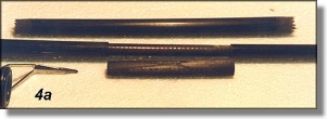
OUTER SLEEVE CONSTRUCTION
This sleeve is made the same as in #3. We have a 5 & 3/4 inches inner plug
and need about 1/2 inch overlap on each end so we need a sleeve about 6 &
3/4 inches long. Size the butt end first but size it with the spacer in
place, then taper the other end and fit it over the tip section splitting as
necessary as we did in #3. Now you have 5 pieces of rod section ready to
bond together - as in picture #4. The outer sleeve must be slipped onto the
tip section, the inner plug gooped and poked through the end of the butt
section. Now install the spacer onto the plug and the plug into the other
(tip) section. The sleeve can now be slipped into place with a liberal
amount of epoxy and wrapped tightly for curing. After the epoxy cures, the
temporary wrap is removed, the area cleaned up and the permanent wrap
installed with your favorite finish. In our illustrated example we removed a
guide which must be replaced. The proper position for the guide falls on the
aft end of the outer sleeve. This is no problem. Simply wrap the sleeve in
entirety, position the guide in its proper location and wrap it in the usual
way - bare thread to bare thread. Now you must be selective with your
finish, the popular so-called high build epoxies will not hack it here. You
need a high penetrating epoxy such as DuraGloss LS or other similar finish.
Otherwise you must wrap the sleeve, apply your epoxy and allow it to cure,
wrap the guide, and apply another coat of epoxy over the whole thing.
Whichever method you choose to follow you should wind up with a finished rod
as in picture #5 and the rod will act and feel like it did before the
accident.
In this type of repair I have attempted several times to make the inner plug
from fiberglass instead of graphite, and the rod always feels mushy. If we
had chosen to shorten the rod by joining the two pieces with no gap to be
filled between them, then fiberglass seems to be satisfactory for the inner
plug. But whenever there is this extension a graphite plug for a graphite
rod is necessary.
Number 5 - Click For Larger View
Number 5. This cheapie should have been thrown away but
sentimentality
overruled mentality. Somebody stepped on the ferrule and that sorta put
things out of round, and that somebody wants to pay for it - so here we go.
Picture of original break got lost, but it showed the ferrule with many
pieces separated and damage extending about 1 &1/2 inches inboard from the
end. This is a male ferrule so we want to restore the original OD as near as
possible. I selected a piece of fiberglass that fit into the ferrule and cut
it to extend 2&1/2 inches into the ferrule and rod. I left about 4 inches
excess for the rod wrapping chuck. I applied a liberal quantity of RodBond
to the reinforcing piece and to the inside of the damage. The piece was
inserted in position and the frayed damage of the original carefully
positioned around it. The ferrule was now wrapped with 'D' thread very
tightly. Wrapping is very slow as the frayed pieces have to be positioned as
you go along. There will be lots of squeeze out which should be distributed
liberally along the entire damaged area. When the RodBond is fully hardened,
remove the thread and clean off the excess adhesive. Install it in your rod
wrapper again and work the surface to a smooth finish with fine files and
320 to 400 grit abrasive paper. Wrapping the broken pieces around the insert
should insure a good round OD, but final smoothing will be necessary. Now
you can test your handiwork by inserting it into its intended place in life
- the female part of the joint. When you are close to a final fit, cut off
the excess and finish it by hand.
FINISHING
The final act will be to coat the entire ferrule with 1 coat of Permagloss,
or an equivalent Urethane. Why Urethane? Because urethanes have the best
abrasion resistance of all the possible coatings that are available to you.
After the Urethane is cured I always coat ferrules with U-40 Ferrule Lube
and they will last much longer as this teflon product eliminates the
friction and wear of a fiber to fiber ferrule and the ferrules will fit much
tighter. And all this for a $9.95 Wal Mart special! Don't expect to get
rich.
CONCLUSION
As many of you have concluded by now, repair work is a labor of love. And I
have found it a lonesome labor. I can find all sorts of builders with
talents far beyond mine, that will readily engage in discussions about
finishes, spine, handle shapes, guides, thread art, (I hate it) any subject
pertaining to building a better and/or prettier rod. But as soon as I broach
the subject of repair I'm looked at like I'm some sort of weirdo that should
crawl back under the rock from whence I came. The conversation now changes
from enthusiasm to boredom with a faint trace of hostility thrown in for
good measure. And not surprisingly, it is from these very same talented
artisans that some of the most pitifully inadequate attempts at repair have
originated. We as rod builders are usually judged as a group. If one very
excellent rod is known to have been constructed by a custom rod builder, the
general public sees ALL custom rod builders as producing the same thing. If
one botched up repair job is known to have been botched by a custom rod
builder, then ALL custom rod builders botch repair jobs.
Repair is certainly not the most glamorous aspect of the custom rod
builders' art, but it is becoming increasingly more in demand so it behooves
us to recognize this fact and learn to do it correctly - or at least
acceptably. ~ Ralph O'Quinn
|
| |